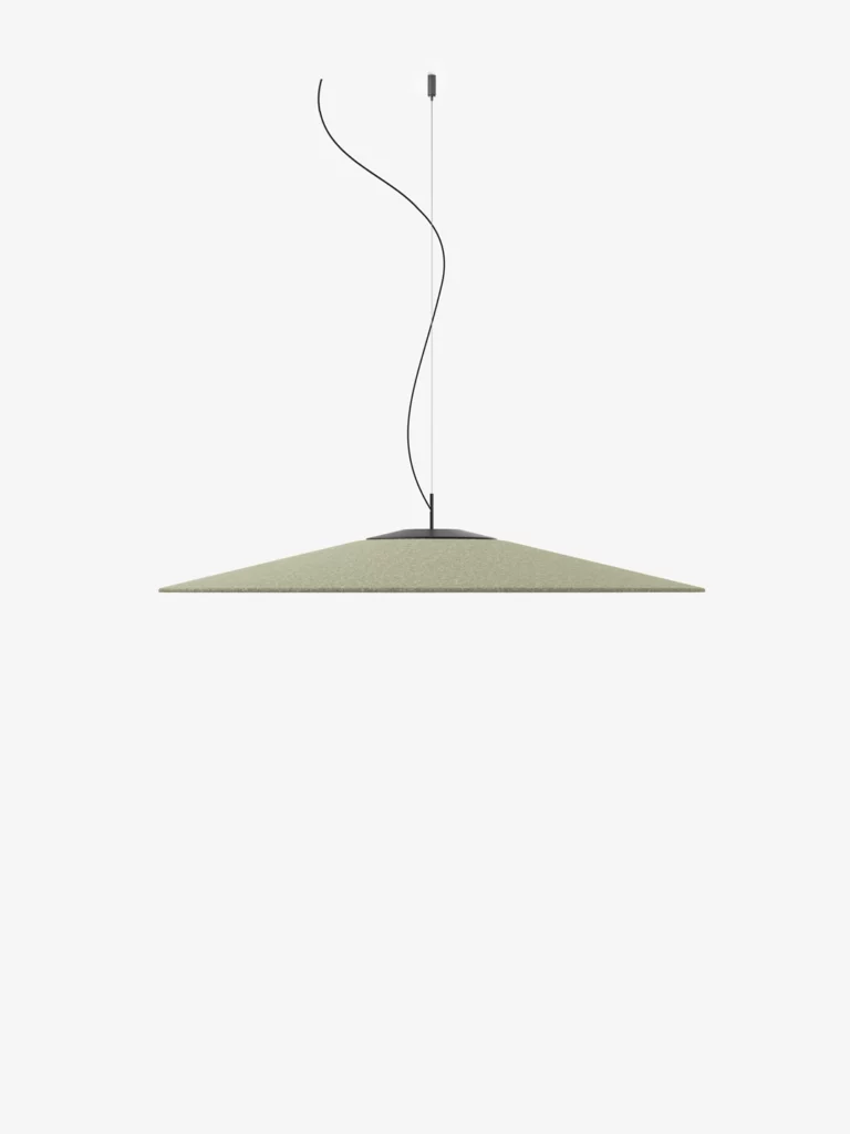
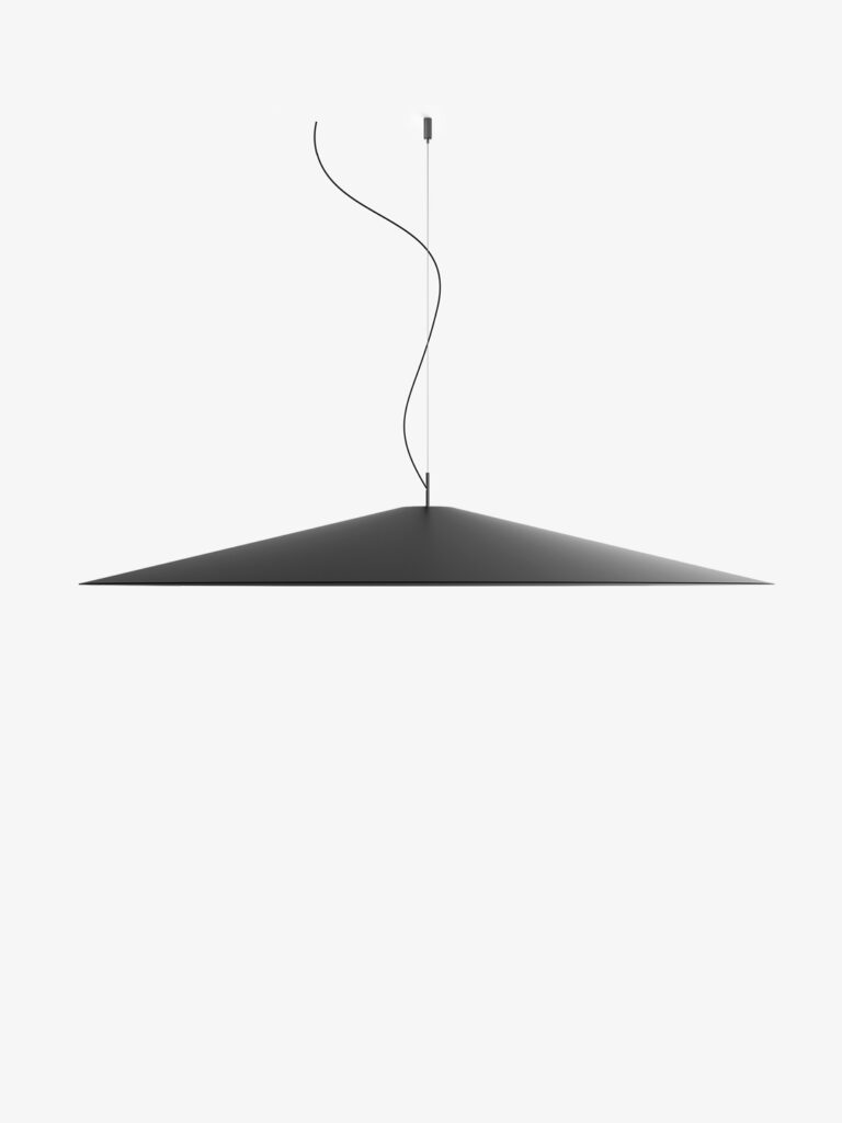
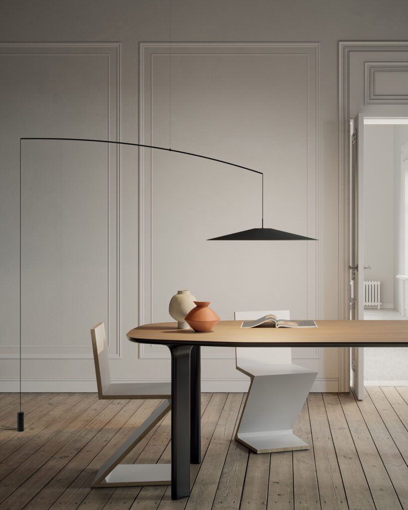
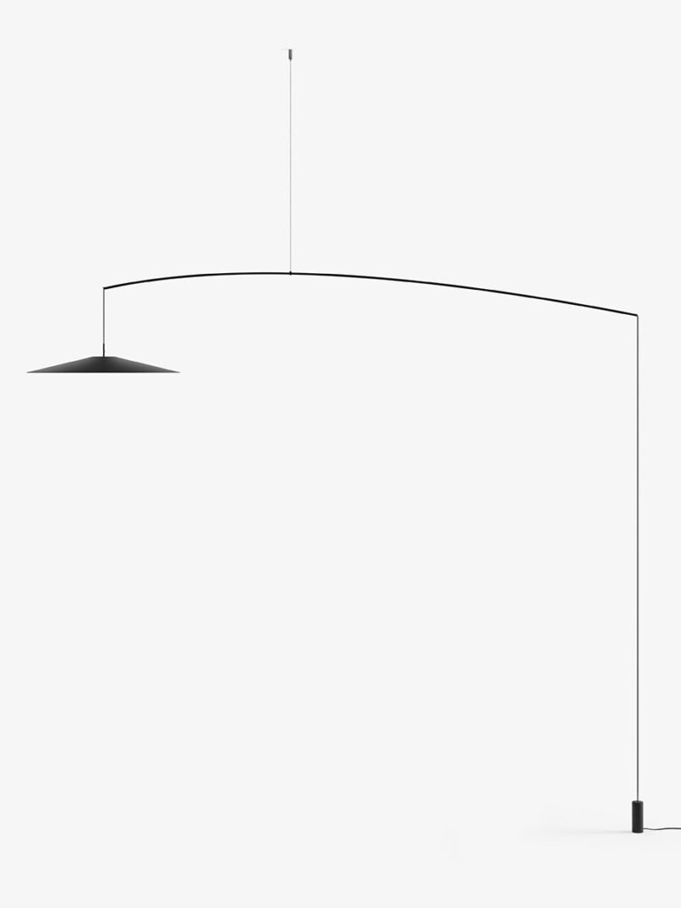
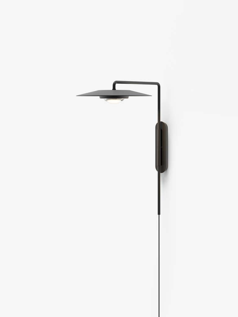
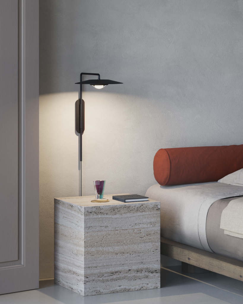
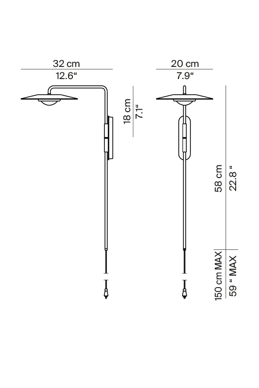
CAD Archives - RoboDK blog https://robodk.com/blog/category/cad/ News about RoboDK, Industrial Robots, Simulation and Robot Programming Wed, 04 Oct 2023 15:40:15 +0000 en-US hourly 1 Moving Robot CAD to the Cloud: The New Onshape Plugin for RoboDK for Web https://robodk.com/blog/onshape-plugin/ Tue, 03 Oct 2023 14:03:15 +0000 https://robodk.com/blog/?p=6579 What if you could combine the power of the world’s fastest-growing cloud-based CAD system with RoboDK’s robot programming capabilities? With RoboDK’s new Onshape Add-in, it’s now possible! The software landscape …

The post Moving Robot CAD to the Cloud: The New Onshape Plugin for RoboDK for Web appeared first on RoboDK blog.

]]>
What if you could combine the power of the world’s fastest-growing cloud-based CAD system with RoboDK’s robot programming capabilities? With RoboDK’s new Onshape Add-in, it’s now possible!

The software landscape for manufacturing is ever-changing. New tools arrive all the time, either to fill gaps in the market or to make better use of the new technology.

Onshape is one such tool. Unlike traditional computer-aided design (CAD) packages, it is entirely browser-based. By using a cloud solution it brings another level of flexibility to manufacturing design.

RoboDK’s team also realized the need for reliable browser-based software. That’s why they released RoboDK for Web back in 2022.

With this new plug-in for Onshape, you can now create product designs and robot programming simulations entirely within your computer’s web browser!

What Is Onshape?

Founded in 2012, Onshape offers cloud-native CAD software. This provides its users with a centralized repository of all design data, making it easy to access, manage, and share design projects from anywhere.

With over two million users, Onshape is very popular. It recently claimed the top spot as the world’s fastest-growing CAD system. It is growing around seven times faster than the average in the market.

Onshape aims to cater to both the specific needs of core engineering teams and non-CAD users. With its wealth of collaboration and agile manufacturing features, it helps foster teamwork from the conception of new products to production.

If you hadn’t heard of Onshape before reading this article, you will almost certainly start hearing about it more. With the growing popularity of collaborative document writing systems, it seems likely that real-time collaborative CAD design will soon become commonplace.

Why Choose Onshape?

As a cloud-based CAD system, Onshape offers a variety of benefits for engineers and designers.

Here are some benefits using Onshape:

Cloud-based Solution

One major benefit of the system is that it eliminates the need for expensive hardware.

As the software is not installed locally, you only need a computer with the capability to run a compatible web browser. You don’t need extensive storage space to hold large project files because everything is stored in the cloud.

Collaboration and Sharing

Onshape is sometimes referred to informally as the “Google Docs of CAD” due to its powerful collaboration features.

You can easily share your CAD designs with both licensed and non-licensed users of Onshape. Non-licensed users can simply view the designs. Licensed users with shared file permissions can simultaneously edit designs in real-time.

Stability and Software Updates

Onshape also stands out thanks to its stability, regular updates, and free learning resources.

Regular updates are released every few weeks and the company provides a live link to check the application’s status and diagnose network issues.

If you do have any issues with the software, Onshape provides extensive training resources and it is supported by an active user community.

Introducing… the New RoboDK Onshape Plugin

What if you could combine the power of cloud-based CAD with a similarly powerful browser-based robot programming?

This is where the RoboDK plug-in for Onshape comes in!

In the plugin, you simply export your CAD file from Onshape and it will show up in the RoboDK window.

Unlike some of RoboDK’s other plug-ins, which are designed for the desktop version, this one works with RoboDK’s online tool: RoboDK for Web.

RoboDK’s CEO Albert explains:

“As with all our plugins, the Onshape plugin is free. We have integrated it with the free-to-use RoboDK for Web. Once you install the App, a window in RoboDK for Web will show that it has been embedded. We are also adding project templates to our library to make it very easy to get started with robot simulation and programming directly from Onshape.”

RoboDK for Web is designed for creating quick proofs of concept and sharing robot simulations. If you want access to more features, you can then download your project directly to RoboDK for Desktop to keep working on it further.

Is This Plugin Right for You?

If you are already using Onshape and you’re looking to get into robot programming, this new plug-in is a must-have!

If you are new to RoboDK, now is a brilliant opportunity to explore it. With RoboDK’s extensive training library and supportive user community, it’s easy to get started with robot programming even if you have never done it before.

If you haven’t tried Onshape yet – maybe you’re a RoboDK user looking for a new CAD software – you can test it to see if it is the right solution for you.

One factor to consider is how important it is that your CAD software is collaborative. Onshape’s real-time collaboration features can certainly be helpful if you are working with remote teams.

How to Get Started Using the New Onshape Plugin

Wondering how you can try out the new Onshape plug-in for yourself?

The best way to assess if it meets your needs is just to try it for yourself! Make a robotic simulation with your Onshape CAD design and see how easy it is to transfer your design into the software for robotic simulation.

You can install the RoboDK plugin from Onshape’s App Store. You may need to create an account with Onshape first. Then, you can try Onshape and RoboDK for free. You can find more information in the RoboDK documentation.

What questions do you have about the new Onshape plugin? Tell us in the comments below or join the discussion on LinkedIn, Twitter, Facebook, Instagram, or in the RoboDK Forum.. Also, check out our extensive video collection and subscribe to the RoboDK YouTube Channel

The post Moving Robot CAD to the Cloud: The New Onshape Plugin for RoboDK for Web appeared first on RoboDK blog.

]]>
New plugin from RoboDK and BobCAD-CAM makes robot machining easy https://robodk.com/blog/robodk-plugin-for-bobcad-cam/ https://robodk.com/blog/robodk-plugin-for-bobcad-cam/#respond Mon, 01 Aug 2022 12:30:00 +0000 https://robodk.com/blog/?p=5583 Software providers RoboDK and BobCAD-CAM have announced their partnership by releasing a new plugin that allows machinists to program robots quickly and easily for machining applications. This new tool promises …

The post New plugin from RoboDK and BobCAD-CAM makes robot machining easy appeared first on RoboDK blog.

]]>
Software providers RoboDK and BobCAD-CAM have announced their partnership by releasing a new plugin that allows machinists to program robots quickly and easily for machining applications. This new tool promises to make robot machining more accessible to machinists and could herald a whole new era in flexible machining for many manufacturers.

RoboDK, a robotics software company based in Montreal, Canada, has recently partnered with BobCAD-CAM, a computer aided design and machining company based in Florida, USA. This month, they have released a new plugin for the BobCAD-CAM software that allows machinists to program robots quickly and easily for machining applications. The two companies hope to make robot machining more accessible to machinists, who traditionally are unfamiliar with robotics and often uncertain about automation.

“The plugin opens more avenues for BobCAD-CAM users to use their software for more applications,” says Jérémy Brouillard, RoboDK’s Product Manager. “We hope that many BobCAD-CAM users are interested in jumping into robot programming. They now have a streamlined workflow with RoboDK.”

Why large work envelope machining is expensive

Some machining operations require a very large working envelope. For example, milling the aluminium casings of airplane wings requires huge, custom-built CNC machines.

For some companies — such as multinational aerospace manufacturers — it makes sense to invest in such machines, which can easily cost millions of dollars. However, the cost and required floor space are restrictive for many smaller companies as large workspaces almost always require a custom machine.

Brouillard says, “When you need that larger work envelope, but you can’t justify the price point of a custom CNC, you can go for robot machining. You can create a huge working envelope, by adding a linear axis to the robot, for a fraction of the price compared to a conventional CNC machine of the same size.”

Robot machining: a cost-effective solution

Robot machining is an increasingly attractive application for manufacturers. It involves using a robot to mill the machining paths instead of a conventional CNC machine. The plugin creates the bridge for machinists to access this new flexible form of machining.

Some machinists are uncertain about machining with robots. Conventional CNC machines are very rigid, accurate, and good at handling dense metals. However, while robots don’t have the high stiffness of conventional CNC machines, they offer several advantages.

First, robots are much cheaper to purchase and operate, particularly for complex projects. Second, they are much more flexible than CNC machines, as they can be programmed to carry out a wider range of tasks. Third, a single machining robot will use a lot less floor space than several conventional CNC machines.

Increasingly, robots are becoming an ideal solution for manufacturing businesses that want to reduce machining costs and increase machining flexibility.

How the new RoboDK plugin for BobCAD-CAM works

The RoboDK plugin for BobCAD-CAM is now available for all users with both software packages. This powerful plugin combines the robust machining-focused features of BobCAD-CAM with RoboDK’s powerful robot programming features. Users can now seamlessly generate robot machining paths right from within the familiar BobCAD-CAM interface.

BobCAD-CAM is a powerful mechanical design and machining software targeted at machinists. It is available as a stand-alone product or as an add-on to the popular CAD programs Rhino 3D and SolidWorks.

To use the new plugin, users simply install it to their BobCAD-CAM installation. They can then access the main functionality via the new panel that’s added to the BobCAD-CAM user interface. They can send machining paths to the robot at the touch of a button and tweak the robot program within RoboDK if needed.

The future of robot machining

With this powerful plugin, machinists can now easily program robots for a wide variety of machining applications, all from within their familiar BobCAD-CAM interface.

Various applications can benefit from large workspace robot machining. Examples include milling of positives for mold making, large-scale sculptures, trimming of molds, and complex hole drilling. As robot machining becomes more accessible, it seems likely that even more applications will emerge as machinists realize the exciting possibilities of the technology.

Brouillard says, “The CAM software comes up with machining properties like the locations of the points, the right speed for the spindle, the right feed speed for the tool. The plugin and RoboDK then translates these into motions of the robot.”

This exciting new development promises to make robot machining more accessible and could herald a whole new era in flexible machining for many manufacturers.

Future plans

RoboDK continues to look for new ways to make robot programming easier and more accessible for manufacturers. They are thrilled to have partnered with BobCAD-CAM to bring this plugin to the market.

Both companies look forward to seeing the amazing things their customers will create with it.

The post New plugin from RoboDK and BobCAD-CAM makes robot machining easy appeared first on RoboDK blog.

]]>
https://robodk.com/blog/robodk-plugin-for-bobcad-cam/feed/ 0
The Guide to 3D Manufacturing Simulator Software https://robodk.com/blog/guide-to-3d-simulator-software/ https://robodk.com/blog/guide-to-3d-simulator-software/#respond Thu, 19 May 2022 21:42:42 +0000 https://robodk.com/blog/?p=5144 Do you wonder if 3D manufacturing simulator software could improve your processes? It might… But how will simulation help? How can you ensure that you get the most from your …

The post The Guide to 3D Manufacturing Simulator Software appeared first on RoboDK blog.

]]>
Do you wonder if 3D manufacturing simulator software could improve your processes? It might…

But how will simulation help? How can you ensure that you get the most from your simulator without wasting time?

Here’s a clear and concise guide to 3D simulator software for manufacturing businesses.

Simulation software is a thriving and growing market. According to market reports, the simulation software is expected to reach a market value of $26.9 billion over the next 4 years.

There are some very compelling reasons to adopt simulation into some of your manufacturing processes. Firstly, you need to understand what it is and how it can apply to your specific business.

What is 3D Simulator Software and Do You Need It?

Simulation involves using a computer program to model certain aspects of a manufacturing environment. Many systems and processes can be simulated.

Some types of simulation software merely use computer algorithms with very little visual feedback. Moreover, 3D simulation software renders the results of the simulation in a three-dimensional visual model. This is making it easier to understand the data.

However, you might wonder if simulation is really worth it for your manufacturing processes.

Wouldn’t it be quicker just to build the physical system? That way, you might think, you wouldn’t have to mess around with software beforehand. You would immediately start to gather real-world data.

The fact is that you can’t afford not to use simulation.

As we’ll see below, there are many great benefits to using simulation software in your manufacturing processes. Your competitors are already using 3D simulators and gaining those benefits.

5 Types of Simulation for Manufacturing

There are various types of simulation that you can use in manufacturing. Some are 3D simulators while others have simpler visual interfaces with powerful algorithms behind them.

Here are 5 common types of simulators you might use:

1. Robotic Simulation

Robotic simulation allows you to design and simulate automated applications involving robot systems. A good robot simulator will support many robot brands and allow for simple but powerful simulations.

RoboDK is an example of a feature-filled robotic simulator.

2. FEA Simulation

A common simulation step during product design, finite element analysis (FEA) allows you to test the effect of physical stresses on materials.

In addition, good FEA simulation software makes it easy for you to proactively improve your designs.

3. CAD/CAM Modeling

An extremely common form of 3D software, CAD/CAM packages allow you to design your products in a computer environment.

Computer-aided design (CAD) functionality focuses on the initial design phase. Computer-aided manufacturing (CAM) functionality lets you simulate the manufacturing process.

4. Discrete Event Simulation

Discrete event simulation (DES) is used to optimize a whole range of manufacturing processes including production process design, facility layouts, and process parameter optimization.

Some DES software packages have 3D interfaces while others only support text-based input and output.

5. Intelligent Simulation

Artificial intelligence (AI) is everywhere these days. This is also true in manufacturing simulations where the use-cases for AI are growing steadily.

Intelligent simulation uses AI to improve the quality of simulation for many different applications including product development, management, and automation.

How to Start Using Manufacturing Simulation the Easy Way

How can you start using simulation software in your manufacturing business?

A good place to start is to remember that you don’t have to simulate everything. In fact, trying to simulate everything would be a bad idea — it would waste a lot of time and make your operations unnecessarily complex.

It’s much easier to identify a particular part of your process that you want to improve and focus exclusively on simulating that.

Thus, a good candidate is robotic automation.

Manufacturers are often hesitant to start using robots. Furthermore, they are unsure how the robot will fit in with their existing processes.

A good robot simulator lets you see the robot in action on a specific target application. It’s an easy, low-cost way to validate that robotic automation is the right choice before you invest in any physical robotic hardware.

7 Great Benefits You’ll See When You Use 3D Simulation

How will adding 3D simulation make your operations better?

Here are 7 great benefits you can see when you start using manufacturing simulation software:

  • Faster time to market — Simulation is almost always faster than testing ideas out in the real world. This means you can smooth out potential problems early and get your new products and updates to market much faster.
  • Less costly downtime — Working with a simulation means you are not taking your physical processes out of production to make changes. This is why robotic simulation and offline programming can save you lots of costly downtime.
  • Easier and quicker to change out components — Changeovers are a huge source of wasted time and resources in manufacturing environments. A robot simulator, for example, allows you change your robot’s task very quickly or even switch it with a completely different robot.
  • Reduced inventory — Excess inventory is one of the major wastes in manufacturing. Simulators help you to optimize your material handling processes, reducing costly inventory buildup.
  • Better information about your processes — The more data you gather about your process, the better you can optimize those processes. Simulators start giving you this valuable data from early on in the design process.
  • Spot and rectify inefficiencies — It’s often hard to see problems and inefficiencies in an already-running system. Simulators make it easier to spot and debug inefficiencies early. For example, RoboDK will automatically flag up singularities, which are hard to spot in a physical robot.
  • Use fewer resources to run your facility — The more you leverage your simulations, the less likely you are to have people running around your manufacturing facility trying to reactively fix problems. This makes your facility more efficient overall.

Which Type of 3D Simulator to Try First

Which of the various types of manufacturing simulators should you start using first?

This really depends on your situation. Try to identify which aspects of your manufacturing process are most inefficient and which will have the biggest impact by improving the process.

Finally, if you are implementing robotic automation, check out our simulator page to find out about robot simulation.

What aspect of your manufacturing process would you like to simulate? Tell us in the comments below or join the discussion on LinkedIn, Twitter, Facebook, Instagram, or in the RoboDK Forum.. Also, check out our extensive video collection and subscribe to the RoboDK YouTube Channel

The post The Guide to 3D Manufacturing Simulator Software appeared first on RoboDK blog.

]]>
https://robodk.com/blog/guide-to-3d-simulator-software/feed/ 0
9 Popular CNC Post Processor Editors You Might Consider https://robodk.com/blog/cnc-post-processor-editors/ https://robodk.com/blog/cnc-post-processor-editors/#respond Tue, 29 Mar 2022 14:10:48 +0000 https://robodk.com/blog/?p=4893 What do you do when you need to edit your CNC or robot post processor? A post processor editor can make the whole process a lot easier… if you use …

The post 9 Popular CNC Post Processor Editors You Might Consider appeared first on RoboDK blog.

]]>
What do you do when you need to edit your CNC or robot post processor? A post processor editor can make the whole process a lot easier… if you use the right one.

Post processors are like the bridge between your simulation package and your physical machine. They automatically turn the graphical simulation into code that your robot or CNC machine can understand.

Most of the time, you won’t need to edit your post processor — it will just work “out of the box.” However, there are times when you need to configure some particular aspects of the post processor. In these cases, a dedicated editor can be a useful tool.

There are a few post processor editors available. The vast majority are incorporated into the software that they are used for. For example, a CAD/CAM software that can control a particular CNC machine may have an editor for its own post processors.

Some programs don’t include a post processor editor at all. So, if you’re looking for one for your particular CAD/CAM system, you might not always be in luck.

Let’s have a look at the various post processor editors you might be looking for…

1. RoboDK’s New Post Processor Editor

First, a rather unique post processor editor!

Many of the other editors in this list are only suitable for CNC machines. They are bundled with CAD/CAM software and only work for this specific type of machine. This can make them rather inflexible.

RoboDK is a robot programming software. It is compatible with robot machining, which can have better performance than CNC machining in some aspects. The post processor editor allows you to quickly and easily configure over 700 robot models with over 80 post processors.

You can find out how to use the RoboDK post processor editor on our documentation page.

2. Alphacam Post Processor Editor

Alphacam is an intelligent CAD/CAM software aimed at woodworking, metal cutting, and stone cutting applications. It supports various CNC machines through its ALP file post processors.

Like many CAD programs, there is no real post processor editor for Alphacam. You have to edit the program’s post processors using a standard text editor. However, there are various resources available online to show you how to edit Alphacam post processors.

3. Gibbscam Post Processor Editor

Gibbscam is a single CAM software solution that claims to work with any CNC machine for either single or multi-axis machining.

To edit post processors for Gibbscam, you need to use the Compost software from the company. According to some reports, this software is not so easy to get a hold of and it can be confusing as there are various conflicting versions of the software.

4. BobCAD-CAM Post Processor Editor

BobCAD-CAM describes itself as a powerful and affordable CAM software. It is compatible with the SolidWorks CAD software and Rhino3D.

There are 2 options for post processor editing in BobCAD-CAM: direct text file editing or a VBScript-based scripting API for more advanced users. The company also offers a whole tutorial on post processor editing, which is helpful as many software providers leave you to work out the process for yourself.

5. PowerMILL Post Processor Editor

PowerMILL is a high-speed and 5-axis machining software provided by Autodesk, one of the leading providers of manufacturing software.

Post processors in PowerMILL are available for a range of CNC machines and even some robots, but the editing process is different for both. There is no dedicated post processor editor so you have to edit the XML files directly.

6. SolidCAM Post Processor Editor

SolidCAM is an integrated CAM solution with a large library of post processors for CNC machines and controllers. It is compatible with SolidWorks and Inventor.

Like many CAM packages, the post processors are not the easiest to edit as the idea is that you shouldn’t need to edit them. Post processors are written in the GPP file format, which mostly consists of IF statements, and need to be edited in a text editor.

7. Autodesk Post Processor Editor

As well as PowerMILL mentioned above, Autodesk also offers various other CAD/CAM software packages, including Inventor and Fusion 360.

Post processors are cross-compatible with Fusion 360 as well as several of Autodesk’s programs. They can be edited using the dedicated editor extension for Visual Studio Code. This adds functions that make it easier to edit post processor files within this familiar coding environment.

8. CAMWorks Post Processor Editor

CAMWorks is a feature-based CAM software that is designed for adaptable automation. It is provided by SolidWorks.

CAMWorks is one of the few packages that offers a post processor editor that rivals the RoboDK editor. Just like RoboDK’s editor its Universal Post Generator has a flexible, graphical interface that allows you to quickly customize post processors and generate error-free code.

9. SolidWorks Post Processor Editor

SolidWorks is a highly popular CAD/CAM system from Dassault Systemes. If you are looking for a post processor for SolidWorks, you can also use the CAMWorks Universal Post Generator.

However, there is also another option. Instead of using CNC machines for your machining processes, you could consider robot machining. This is more flexible than conventional machining and you can use the RoboDK post processor editor to configure your chosen robot.

Learn more about robot machining in our introductory article.

What post processor editor do you tend to use? Tell us in the comments below or join the discussion on LinkedIn, Twitter, Facebook, Instagram, or in the RoboDK Forum.. Also, check out our extensive video collection and subscribe to the RoboDK Youtube Channel

The post 9 Popular CNC Post Processor Editors You Might Consider appeared first on RoboDK blog.

]]>
https://robodk.com/blog/cnc-post-processor-editors/feed/ 0
CNC Robot Programming in 7 Easy Steps https://robodk.com/blog/cnc-robot-programming/ https://robodk.com/blog/cnc-robot-programming/#comments Fri, 03 Sep 2021 21:05:50 +0000 https://robodk.com/blog/?p=4447 Is CNC robot programming easy enough that you should consider a machining robot? You’re looking to improve your CNC process… Should you just purchase another conventional CNC machine? Sure, it …

The post CNC Robot Programming in 7 Easy Steps appeared first on RoboDK blog.

]]>
Is CNC robot programming easy enough that you should consider a machining robot?

You’re looking to improve your CNC process…

Should you just purchase another conventional CNC machine? Sure, it ties you to particular machining processes, but at least CNC programming is familiar to you…

Or could a machining robot add some extra flexibility and advanced functionality that will be beneficial to your business?

It’s easier to program a robot for CNC-style machining than you might think.

Are Robot Programming and CNC Programming Comparable?

First, it’s worth discussing whether it’s even correct to talk about using a robot for machining tasks.

Some people assert that robots shouldn’t be used for CNC machining as they don’t match the performance. However, this is a rather narrow way of thinking. It prioritizes certain measures of performance at the expense of other measures of performance.

While it’s certainly true that CNC machines have higher stiffness and accuracy than robots, they don’t excel in all properties. For example, robots are more flexible and have a bigger workspace. This allows them to handle machining tasks that would just be impossible for a conventional CNC machine.

We have talked before about the properties in which robot machining can outperform CNC machines.

Even so, it’s important to note that not all machining tasks are suitable for robotic machining. CNC machines exist for a reason and they are very good at what they do.

For some specific situations, robot machining can be an extremely effective way to add more versatile machining capabilities to your operations.

The Importance of a Good Robot Programming Tool for CNC

If you do decide that robot machining is right for your machining needs, there is one important choice that you will need to make up-front…

Which programming tool will you choose?

One reason that robot machining is a relatively new application of robotics could be because of the traditional difficulties with programming.

Programming even a simple CNC machining toolpath requires the robot to make a lot of movements. Traditionally, these would have been extremely difficult to program.

These days, some robot programming tools make it easy to create CNC robot machining programs through a dedicated machining wizard.

7 Easy Steps to Program Your Robot as a CNC Machine

Programming your robot to operate in place of a CNC is easier than you might think. You just need to get the right steps in place.

Here are 7 simple steps for reliable CNC robot programming:

1. Assess If Your Task is Suitable for a CNC Robot

CNC robots and conventional CNC machines are best suited to different types of machining. There are a few key properties that you should consider before choosing to go with one technology over the other.

Before you move forward with the deployment, decide if a robot will be suitable for your machining task.

2. Identify the Right Robot Model for Your Needs

Only some robot brands and models will be right for your machining task. You will need to select a model that suits your needs.

One property that is important for robot machining is the stiffness of the robot. Choose a robot with sufficient stiffness that its mechanical structure will not produce unhelpful vibrations.

3. Load Up the Software

Once you have identified the right robot for your CNC machining task, you just need to load up your chosen robot programming software.

If you’d like to try RoboDK, you can download your free trial copy via the download page.

4. Select Your Robot Model in the Library

Adding your chosen robot model is a simple case of going to the Robot Library and picking it from the list of available robots. We currently have over 600 robots and accessories from over 60 manufacturers.

If your chosen robot isn’t listed, just get in contact and we can add it for you.

You will also need to add your chosen machining tool to the robot setup. There are some already available in the library or you can add your own.

5. Connect With Your CAM Tool

The “business end” of your CNC robot programming will be in your CAD/CAM tool. If you’ve been using conventional CNC machines, you will be familiar with the interface of your favored CAD software.

Any CAM tool can be used to generate the machining toolpaths for CNC robot machining. But, RoboDK does have plugins for various popular CAD/CAM software packages.

6. Run the Machining Wizard

Programming the robot to follow your machining path is very easy. You just load up the RoboDK machining wizard and add your CNC file.

There are various settings you can also choose here including the tool offset, approach and retract normals, and your preferred algorithm. You can find more specific details in the documentation.

7. Download Program to the Robot

Finally, you simply need to generate your CNC robot program and download it to the robot controller itself. This can be done at the click of a button.

The robot can then follow your programmed machining path.

A Tutorial to Get Started With CNC Robot Programming

How can you get started quickly with your CNC robot programming?

A reliable way to learn how to use a new software is to watch an experienced user creating a robot machining program from scratch.

We have several dedicated video tutorials where experts from our team show how you can create a machining application easily in RoboDK. These include applications like machining with an external axis, laser cutting, 3-axis machining, and plastic deburring.

What’s stopping you from getting started with robot machining? Tell us in the comments below or join the discussion on LinkedIn, Twitter, Facebook, Instagram, or in the RoboDK Forum.

The post CNC Robot Programming in 7 Easy Steps appeared first on RoboDK blog.

]]>
https://robodk.com/blog/cnc-robot-programming/feed/ 1
Proptogroup Uses RoboDK to Make Amazing Sculptures https://robodk.com/blog/sculptures-proptogroup/ https://robodk.com/blog/sculptures-proptogroup/#respond Mon, 12 Apr 2021 11:00:00 +0000 https://robodk.com/blog/?p=4002 If a client came to you with a completely different type of project that pushed the limits of your capabilities, what would you do? And what if they had strict …

The post Proptogroup Uses RoboDK to Make Amazing Sculptures appeared first on RoboDK blog.

]]>
If a client came to you with a completely different type of project that pushed the limits of your capabilities, what would you do?

And what if they had strict budget, time, and logistical constraints?

This is the type of challenge that Proptogroup handles every day.

In two of Proptogroup’s latest projects, they utilized RoboDK’s robot programming flexibility to create some amazing sculptures for two of their clients.

Here’s how they did it…

Introducing… Proptogroup

Proptogroup is a multi-disciplinary design studio (located in New York, USA) and fabrication studio (based in New Haven, USA). They most often work with artists, architects, designers, and builders on complex projects with critical constraints, whether those be timing, budgetary, or logistical constraints.

For this reason, Mena Henry, Proptogroup’s owner and principal engineer, describes the company as “a problem-solving creative space.”

When you enter their workshop, it is filled with fabrication machines: milling machines, various metal fabrication machines, a welding station, and two converted shipping containers at the end of the space that house a design studio and a materials store.

And then there’s the robot…

Finally, Henry explained the origins of the company’s name:

“The name Proptogroup starts with the word “prop. to.” Mathematically, it means “proportional to.” In this case, it’s about the proportional relationship of different industries, particularly in architecture and construction. Those are design, engineering, fabrication, installation, and logistics. We service all those trades.

Making complex sculptural work requires a lot of research and development, and material science. We count on partners that can enhance our skills. The small size of our company gives us an extreme level of flexibility and mental room to explore and play around.

Actually, playing of the biggest things that we do here, either with material or with technological processes. That really enhances the way that we think and are able to function with complex projects. “

Proptogroup uses RoboDK for Foam Architecture and Clear Acrylic Face

The two projects that we are exploring here are perfect examples of Proptogroup’s cross-disciplinary approach. Indeed, one is for the architectural space and the other is an artistic sculpture.

Foam Architecture

For the foam architecture, Proptogroup employed RoboDK to help them with robotic milling of a foam structure.

As shown above, the structure was made of expanded polystyrene (EPS) foam. In fact, this is a common material for robotic milling as it is easy to mill, has low moisture absorption, and doesn’t change its physical properties under normal operating heat. Such foam is often used, for example, in Hollywood to make architectural props for movies.

In this case, the EPS foam was being used as a form for a mold. The final piece would then be cast, using this mold, in glass fiber reinforced concrete (GFRC).

Acrylic Face Sculpture

The second project was a sculpture for artist Titus Kaphar. Kaphar is a painter, sculptor, filmmaker, and installation artist whose work examines the history of representation. Therefore, he often combines materials and fabrication methods.

In this case, Proptogroup has worked with Kaphar on several projects over the years. This latest one was the face of Thomas Jefferson sculpted in acrylic. They used robotic milling to sculpt the head and then a final manual polishing process.

Mena Henry explained:

“We took our time milling the acrylic considering the brittleness of the material. Timewise, I would estimate approximately 40 hours from roughing to finish pass. And 4 days of hand polishing.”

Proptogroup’s Robot Setup

Mounted on a rail and taking a prominent place in the workshop, Proptogroup’s large KUKA robot is, I think it’s fair to say, a centerpiece to their operations.

The Hardware

For the milling operation, the robotic hardware that Proptogroup used consisted of:

  • A KUKA 6 DoF industrial robot
  • A Güdel linear rail
  • A milling head

Proptogroup will change the end effector of the robot depending on the fabrication needs of the particular project. No project is exactly the same so they need to remain flexible.

The Software

For programming the robot, Proptogroup used the following programs:

  • Design was done in Rhino, a CAD package often used by architects.
  • Machining paths were generated in Autodesk Fusion 360, a popular CAD/CAM software.
  • Proptogroup uses RoboDK to seamlessly convert the machining paths into robot programs.

This software setup gave Proptogroup the flexibility to use the software that they are most comfortable with the power of RoboDK’s robot programming capabilities (actually, they might have been able to eliminate a step as RoboDK has a plugin to work directly with Rhino, but RoboDK fits in with whatever workflow our users most prefer).

How Proptogroup uses RoboDK to Mill an Intricate Face Sculpture

After all, RoboDK allowed Proptogroup to quickly turn their designs into a functional robot program.

In fact, conventional robot programming methods requires to have extensive robotics expertise to program the robot. Instead of focusing on the design and fabrication – which is where Proptogroup’s expertise lies – they would have had to waste a lot of time and effort “getting the robot to work” if they were using the conventional methods.

As a result, Proptogroup reduced robot programming to a minimum using RoboDK.

Indeed, the software easily slots into your existing workflow, whatever that may be, and allows you to focus on those aspects of the process that you are best at.

What Interesting Project Could You Use RoboDK for?

Overall, Proptogroup undertakes many interesting projects that push the boundaries of fabrication techniques under critical constraints.

If they can create such elaborate and successful projects using RoboDK… think what interesting projects you could achieve!

How could your next robotic fabrication project push the boundaries of what you are currently capable of?

Finally, a good place to start is to download a free trial copy of RoboDK and try it out for yourself.

What will your next robot project be? Tell us in the comments below or join the discussion on LinkedIn, Twitter, Facebook, Instagram, or in the RoboDK Forum.

The post Proptogroup Uses RoboDK to Make Amazing Sculptures appeared first on RoboDK blog.

]]>
https://robodk.com/blog/sculptures-proptogroup/feed/ 0
How to Convince Management to Agree to Robot Machining https://robodk.com/blog/convince-management-robot-machining/ https://robodk.com/blog/convince-management-robot-machining/#respond Tue, 15 Dec 2020 14:17:56 +0000 https://robodk.com/blog/?p=2345 You might see the benefits of robot machining… but does your boss? Here’s how to convince management to approve your robot machining project. Have you ever had great ideas you …

The post How to Convince Management to Agree to Robot Machining appeared first on RoboDK blog.

]]>
You might see the benefits of robot machining… but does your boss? Here’s how to convince management to approve your robot machining project.

Have you ever had great ideas you wanted to share with your boss on how you can improve your business?

We can see the benefits that a new technology or approach will bring to our workshop. But, management might say that there’s “not enough budget” or “not enough time.”

Robot machining can be a game-changer for your business. A machining robot can simplify your life and even outperform traditional CNC machines.

You are probably aware of the benefits that robot machining can bring to your workshop or production line. Still, management might not be so convinced… or at least, not yet!

Here’s how you can convince management to get your robot machining project approved.

Why Management Might Not Agree to Robotic Machining

Imagine you go to your boss with a proposal to start using robotic machining… and they say no.

What reasons do you think they might have for this rejection?

In these situations, we are often quick to blame the management. We might say that they are “blind to new technologies” or they are “too focused on cutting costs.”

While these may have an element of truth in some rare cases, they are quite unlikely. In most cases, people who are in management are very committed to making the business successful. It is in their interest to make the business run as effectively as possible.

Although you can probably see the benefits of robotic machining, they might be more likely to look at the risks.

5 Common Concerns About New Robotic Technology

In the first place, your boss probably doesn’t hear the benefits of robotics. Instead, they hear “new robotic process” and think of any one of many problems, including:

  • “It costs too much”. Probably the most common concern. For many, automation equates with high cost.
  • “The ROI is long and uncertain”. Managers might think about Return on Investment instead of the up-front cost. They’ll be put off if they can’t see a clear payback time or they think it will be too long.
  • “We’re too busy with other operations”.Instead of the potential time-saving benefits that robot machining could bring, your boss is thinking of all staff hours that it will take.
  • “Automation will be unpopular”. — The media is filled with stories about “robots taking jobs”. Management might think that the workforce will resist.
  • “We don’t need robot machining.” — You are probably proposing robot machining as an alternative to existing manual or CNC processes. However, management might not see why a robot is any better than what you have already.

It’s important to address these concerns directly rather than ignoring them. Management is much more likely to accept your proposal when you demonstrate that you have understood their concerns. Even better, you have come up with a strategy to overcome them.

6 Steps to Ensure a Successful Proposal

Creating a successful proposal for robotic machining requires several preparation steps.

That means that you need to do a bit of “homework” if you want your proposal to be accepted.

Here are 6 steps to build a watertight proposal that will convince management that robotic machining is a good solution:

  • Assess the suitability of robotic machining. Before presenting your solution to management, you first need to be sure yourself. Take some time to clarify the specific problems that robotic machining will solve.
  • List the benefits and tangible improvements.If you’ve been looking into robotic automation for a while, you probably have an intuitive feeling. List the potential benefits to your manufacturing process and, where possible, add specific numbers to them.
  • Find out what is important for your boss. You will have a much better chance of having your proposal accepted if you present the benefits in a way that directly speaks to your boss’s main concerns. For example, if they’re always talking about cutting costs or increasing production it’s likely that these are important to them.
  • Convert the benefits into language they will understand.This is where the “Jedi Mind Trickery” of the process comes in… well, okay maybe not quite mind trickery. However, you will skyrocket your chances of success if you “translate” the benefits in a way that directly speaks to your boss’s top concerns. For example, if your boss is most concerned about growing the business, instead of saying that robotic machining will “make machining more flexible” you could say “allow us to produce bigger workpieces which would allow us to serve new markets.”
  • Build and rehearse your proposal. Every proposal, no matter how small, can benefit from some good rehearsal. For instance, you can write down the proposal but also make sure that you can present it out loud with confidence.
  • Present your proposal and follow-up. Having done the “homework” you can now present your case for robotic machining to the management. Make sure to answer any questions and follow up by sending details of the proposal in writing.

Improve Your Chances of Success With a Simulation

A picture is worth a thousand words, they say.

How many words do you think a functional simulation of the robot is worth? Probably millions!

Finally, you can improve your chances to convince management to robot machining even further: Create a simulation of your application in RoboDK. Check out how to create a robot machining simulation and robot program in just a few steps.

You can also learn more by trying our plugins for Autodesk Fusion 360, Mastercam, Autodesk Inventor or MecSoft/RhinoCAM.

Have you ever had a proposal knocked back by management? Why did it happen? Tell us in the comments below or join the discussion on LinkedIn, Twitter, Facebook, Instagram or in the RoboDK Forum.

The post How to Convince Management to Agree to Robot Machining appeared first on RoboDK blog.

]]>
https://robodk.com/blog/convince-management-robot-machining/feed/ 0
Case Study: Abstract Building Facades With Robot Fabrication https://robodk.com/blog/building-facades-robot-fabrication/ https://robodk.com/blog/building-facades-robot-fabrication/#comments Tue, 11 Aug 2020 20:05:42 +0000 https://robodk.com/blog/?p=3263 Abstract shapes are one of the big challenges for fabrication. But, they are becoming more and more common in architecture. How can architects untie themselves from the restrictions of traditional …

The post Case Study: Abstract Building Facades With Robot Fabrication appeared first on RoboDK blog.

]]>
Abstract shapes are one of the big challenges for fabrication. But, they are becoming more and more common in architecture.

How can architects untie themselves from the restrictions of traditional construction methods?

One research team has found an ingenious way using RoboDK and Grasshopper.

In a world of architecture, easy-to-manufacture shapes have traditionally been made up of regular, straight lines. This is why buildings tend to feature smooth, vertical facades with very little variation from one building to the next.

But, times are changing.

Recently, architects have found ever more ingenious ways to break free from the restrictions of traditional building methods. We are now becoming more familiar with the sight of strangely shaped buildings with interesting, varied appearances.

The facade of the building (its front-facing appearance) is key to creating these interesting shapes. But, it can be difficult to fabricate complex facades in a way that is quick and cost-effective.

This is exactly the problem that one research team has tackled with RoboDK.

Introducing… the Building Envelope Research Group

The Building Envelope Research Group (BERG) is based in the Anhalt University of Applied Sciences in Köthen, Germany.

BERG’s primary focus is to expand the “scope of the building envelope” with new and innovative fabrication methods, looking at materials, construction techniques, technology, and energy. Their current research projects range from methods to create self-sufficient ventilation systems through to the development of bendable acoustic panels.

The group got in touch with us because they were using RoboDK for one of their research projects.

This project used an interesting approach to robot manufacturing to create forms for abstract concrete facades.

Video from Building Envelope Research Group (BERG)

Why Abstract Facades Are Tricky to Fabricate

Many different materials can be used to create a building facade. Common options include wood, metal, stone, and masonry. However, one of the most versatile options is concrete.

Concrete has an advantage over other materials because it is cheap, hard-wearing, and extremely adaptable. As it begins in liquid form, you can create almost any shape that you can imagine… as long as you have a method to hold the shape of the wet concrete as it sets.

The challenge, therefore, comes in the creation of forms to hold the shape of the concrete facade panels. If you want to create interesting abstract shapes out of concrete, you need to create equally interesting abstract forms that are capable of supporting the wet concrete.

Image from Building Envelope Research Group (BERG)

Common options for creating such forms include

  • Creating a mold out of wood, rubber, or metal.
  • Using a flexible table with actuators and membranes to alter its shape.
  • Using a CNC machine to mill a form out of foam or plastic.

These are all good options but they can be expensive and take a long time to create. For example, flexible tables are quick to reconfigure into a new shape, but the upfront machine cost is very high. CNC milled foam takes 5-10 hours to create and can only be reused 5-10 times before they need to be remade.

Why Use Abstract Facades At All?

You might wonder why we want to create abstract facades for buildings at all.

Of course, the main reason is aesthetics — they look good. However, modern facades are not all about aesthetics. The design of the facade can also enhance the sustainability of the building.

Facades are also a great place to test out new fabrication techniques, as the team at BERG demonstrated in their project.

Image from Building Envelope Research Group (BERG)

The Project: Creating Abstract Forms for Fiber-Reinforced Concrete

The team decided to use robot fabrication to create styrofoam molds for the concrete, which was reinforced with glass fibers.

The robot used a hot wire to cut the styrofoam blocks and was programmed via RoboDK.

To handle the abstract shapes, they chose the CAD package Rhino due to its parametric modeling capabilities. Parametric modeling allows designers to create previously unimaginable structures easily and it is often used by architects for this reason. We previously discussed the benefits of using Rhino with RoboDK in our article 6 Amazing Things You Can Do With Rhino and RoboDK.

They first designed their CAD model within Rhino (and its algorithmic modeler Grasshopper) and then used the RoboDK Rhino plugin to send these designs directly to their robot.

As the team at BERG is largely focused on material properties, a major part of this research project involved testing the structural properties of the concrete after it was formed in this way.

One important property was the surface finish. They found that they could vary the detail of the surface finish by changing how quickly they moved the robot. Slower speeds led to a smoother surface finish.

The Robotic Setup

The robotic hardware that the team used was as follows:

  • Robot: A KUKA KR 16-2 6-axis industrial robot.
  • End effector: A metal rig on which was mounted a hot wire to cut the styrofoam.
  • Table: The styrofoam block was fixed to a table, ensuring that it didn’t move during the cutting operation.
  • Programming setup: Rhino and Grasshopper for CAD design and structural (FEA) analysis, attached to RoboDK via the plugin.

Benefits of Using Robot-Fabricated Styrofoam for Facades

There were several benefits that the team found with their method compared to the more standard approaches to concrete facade fabrication.

These included:

  1. It was cheaper — The up-front costs for this method were less than those with other methods of form production. For example, CNC milled forms cost up to €400 per square meter. With this method, the cost was only €30 per square meter.
  2. It was quicker — The time to create the form was only 1 hour. With every other type of manufactured form, it would take between 2-10 hours to create. The only faster option would be to use the costly flexible tables.
  3. It was flexible — Unlike other options, the only limit to this method was the reachability of the robot and the dimensions of the cutting wire. This increases the flexibility of this method.

For more information about this project, check out their research paper.

What architectural projects can you think of for robotic fabrication? Tell us in the comments below or join the discussion on LinkedIn, Twitter, Facebook, Instagram, or in the RoboDK Forum.

The post Case Study: Abstract Building Facades With Robot Fabrication appeared first on RoboDK blog.

]]>
https://robodk.com/blog/building-facades-robot-fabrication/feed/ 1
Boost Robot Machining With RhinoCAM and the RoboDK Plugin https://robodk.com/blog/robot-machining-rhinocam-robodk/ https://robodk.com/blog/robot-machining-rhinocam-robodk/#comments Tue, 31 Mar 2020 13:46:24 +0000 https://robodk.com/blog/?p=2824 The impressive flexibility of Rhino. Plus, the power of a good CAM package. Plus, the robot-programming skill of RoboDK. You can now combine them all with the new RoboDK plugin …

The post Boost Robot Machining With RhinoCAM and the RoboDK Plugin appeared first on RoboDK blog.

]]>
The impressive flexibility of Rhino.

Plus, the power of a good CAM package.

Plus, the robot-programming skill of RoboDK.

You can now combine them all with the new RoboDK plugin for RhinoCAM.

We already have an impressive (and growing) set of plugins for some of the most popular CAD/CAM packages in the business.

But, our newest plugin is quite an interesting one…

It’s a plugin for another plugin!

Let’s have a look at the new RoboDK plugin for RhinoCAM

What is RhinoCAM?

RhinoCAM is itself a plugin for the very popular freeform modeling tool Rhino (aka Rhinoceros or Rhino3D). We already have a plugin that communicates directly with Rhino itself.

RhinoCAM adds additional CAD/CAM capability to Rhino. It is based on VisualCAM, a popular stand-alone CAM package by MecSoft. It runs seamlessly within Rhino, allowing you to easily generate CNC programs from your freeform generated models.

What is RhinoCAM Good For?

One of the key features of RhinoCAM (and VisualCAM itself) is its 5 core modules dedicated to specific CNC manufacturing processes.

These 5 modules are:

  1. RhinoCAM-MILL — The MILL module is designed for processes like molding, die and tooling, woodworking, rapid prototyping, and general machining. It is compatible with 2.5, 3, 4, and 5-axis machining, which is perfect when used in collaboration with RoboDK.
  2. RhinoCAM-TURN — The TURN module is a powerful 2-axis turning center for processes like turn roughing, finishing, threading, parting, and hole machining. It is used with CNC lathes.
  3. RhinoCAM-NEST — The NEST module is an optional add-on module that helps users optimally arrange and fit geometric shapes onto sheets of stock material. It provides two nesting capabilities: rectangular nesting and true nest shaping.
  4. RhinoCAM-ART — The ART module turns artwork into geometries suitable for machining. It can take raster bitmap images as an input. It also has a set of modeling techniques specific to jewelry design, sign making, and model making. This is perfect when used for robotic drawing or engraving projects.
  5. RhinoCAM-MESH — The MESH module is a completely separate module that includes tools for automatically processing 3D mesh data. It can clean up, reduce, refine, and otherwise prepare 3D meshes for applications like NC machining and 3D printing.

These modules form the basis of RhinoCAM’s capabilities and provide a very focused capability for these particular CAM tasks.

Why You Might Want to Use RhinoCAM and RoboDK Together

As you might know, RoboDK is a software that allows you to easily and effectively program your robot for a huge variety of different tasks.

One such task is robot machining which involves using the robot to operate a machining tool. This is like CNC machining but with much more flexibility. There are several benefits to using a robot over a CNC machine as we discussed in our article Can a Robot Outperform a CNC Machine for Robot Machining?

Just as is the case with normal CNC machining, the process starts with a good 3D model produced in a CAD program. Then, you use a CAM program to turn this into a G-Code path that can be machined on a robot or a CNC machine.

RhinoCAM has the capability to generate the G-Code, whilst also performing other functions to optimize the machining process.

RoboDK can then take that G-Code as an input and automatically creates a robot program for your particular robot model.

Together, you can quickly and easily generate machining programs for your robot machining setup.

Introducing… the New RoboDK Plugin for RhinoCAM

As with our other plugins (for Rhino itself, Mastercam, SolidWorks, and Inventor) the main functionality of the plugin is controlled by a standard set of buttons.

It includes the 5 standard buttons for CAD operations (plus an “About” button):

  1. Auto Setup — This creates a new project within RoboDK, along with your 3D from within RhinoCAM and the machining path.
  2. Load Part — Sends the 3D model directly from RhinoCAM to RoboDK.
  3. Load NC Program — This loads the machining program from RhinoCAM into RoboDK. If you are using multiple machining tools, it will create a new program for each tool.
  4. Generate Robot Program — This allows you to generate the robot programs within RoboDK without ever needing to leave RhinoCAM, which will speed up your workflow.
  5. Settings — Customize the plugin by changing tolerances, scales and the exported file type for 3D models. You can also define the names that objects will have when they appear in RoboDK.

Is the Plugin Right for You?

If you’re already using RhinoCAM then I can’t see any reason why you shouldn’t try the new RoboDK plugin! You can get a free demo version on the downloads page.

If you haven’t tried RhinoCAM yet, but you’re using RoboDK and/or Rhino, check out the RhinoCAM website to see if it might be a good match for your machining needs.

How to Get Started Using the New RhinoCAM Plugin

The best way to test the new plugin’s capabilities is to try it out for yourself!

Download the latest version of RoboDK (if you haven’t already) and check out the documentation page, which explains all the functionality of the plugin in detail.

What are your opinions of RhinoCAM? Tell us in the comments below or join the discussion on LinkedIn, Twitter, Facebook, Instagram or in the RoboDK Forum.

The post Boost Robot Machining With RhinoCAM and the RoboDK Plugin appeared first on RoboDK blog.

]]>
https://robodk.com/blog/robot-machining-rhinocam-robodk/feed/ 1
Multi-Axis Robot Machining With the Fusion 360 Plugin https://robodk.com/blog/robot-machining-fusion-360/ https://robodk.com/blog/robot-machining-fusion-360/#respond Thu, 07 Nov 2019 12:10:40 +0000 https://robodk.com/blog/?p=2367 What does a project using the Fusion 360 plugin look like in practice? Here’s how one university fabrication lab Protolab used multiple external axes. We always love hearing from users …

The post Multi-Axis Robot Machining With the Fusion 360 Plugin appeared first on RoboDK blog.

]]>
What does a project using the Fusion 360 plugin look like in practice? Here’s how one university fabrication lab Protolab used multiple external axes.

We always love hearing from users of RoboDK, especially when they are using new features of the software. Often, the first we hear about these great case studies is when a user sends us a question.

Recently, Andrew Tarlinton from Protolab at the Swinburne University of Technology had a question about using robotic milling with the new Fusion 360 Plugin.

Andrew asked: How can I incorporate multiple external axes into my robotic milling project?

Let’s have a look at that project!

Meet… Protolab

Protolab is a fabrication laboratory at the Swinburne University of Technology in Victoria, Australia. The lab provides training and fabrication services to students at the university and has an impressive collection of machines including 5-axis CNC machines, SLA 3D printers, and, of course, robots.

Andrew Tarlinton is the manager of technical services, design, and architecture for Protolab. He has a background in industrial design and scientific instrument making.

The lab serves the university both by providing a space for students to learn about fabrication in a hands-on setting and by providing fabrication services for the university’s many technical projects.

The Project: Multi-Axis Robot Milling Workstation

Fabrication technology is always improving and Andrew is always on the lookout for new and better ways to run the Protolab workshop. He got in contact with us because he was setting up a new robot milling workstation using a KUKA robot.

The setup uses multiple external axes to allow for an extremely flexible robot milling station. At the moment, the team is primarily using this setup for architecture research, but Andrew expects that they will soon start using it for applications like furniture fabrication and possibly creating automotive models.

Hardware Setup

Andrew and the team at Protolab decided on the following robotic technology:

  • KUKA KR 120 — The KR120 is a range of KUKA robots all of which have a payload of 120 kg, but with differing reaches. Many of this range are already within the RoboDK library. The team used the KR C4 Controller which can control both the robot and external axes.
  • KL 4000This is a linear track external axis with a 7.9-meter travel distance and supports payloads up to 4000kg.
  • KP1-V 500 From KUKA’s range of positioners, this is a vertical single-axis positioner with a payload capacity of up to 500 kg. The team uses this as the turntable to hold the workpiece.
  • KP1-H 500Also from the KUKA range, this is a 500 kg payload single-axis positioner which can be used for horizontal positioning.

This combination of 3 programmable external axes with a 6 Degrees of Freedom (DoF) robot provides up to 9 DoF for the team at Protolab to carry out robot milling, with a huge workspace thanks to the 7.9 m distance of the KL 4000.

Software Setup

Despite the complex hardware setup, the software workflow is quite simple:

  1. Fusion 360 — The design of the machined part is done within Autodesk’s Fusion 360, a cloud-based CAD/CAM software which has various advantages over Autodesk Inventor. Once the CAD model is designed, the CAM path is generated within the same software.
  2. RoboDK — Using the plugin for Fusion 360, the robot program can be generated immediately, by using RoboDK’s robot machining capability, without leaving the Fusion 360 software.
  3. KR C4 — The generated robot program is then sent to the KUKA controller, with a program in KUKA’s KRL programming language generated by the relevant post-processor. This controller then moves the physical robot through the milling process.

This is the same software workflow that you would use for any similar robot machining project.

Handling Multiple New External Axes in RoboDK

Andrew Tarlinton initially got in contact with us for some help. The three external axes that he was using provided a great amount of flexibility for larger robot machining tasks. However, he wasn’t sure how to incorporate them into RoboDK.

Our Robot Library already contained the robot (KR 120) and horizontal positioner (KP1-H), but the other two axes were not there yet.

Of course, we can always add new axes, robots, and accessories to the library if you ask us to. However, there was a quick way for Andrew to get his missing axes…

The Solution: Custom Axes and Auto-Sync

RoboDK has a very large library of already-supported robots. But, it can also easily support any other mechanism which is not already in the library. All you need to do is create a custom mechanism by using the “Create Mechanism” tool.

Andrew was able to create the two missing axes as single-axis mechanisms consisting of one linear and one rotative axis.

In RoboDK we can then synchronize the axes. By making one or more mechanisms (e.g. an external axis) the child of another (e.g. the robot), the software will integrate the DoFs of both mechanisms, allowing you to seamlessly control the entire setup as if it were one single mechanism.

Fusion 360 + RoboDK = Seamless Integration

Using Fusion 360 in collaboration with RoboDK — via the plugin — is a great way to achieve robot machining in a familiar software environment (if you are already a user of Fusion 360, of course).

As Andrew Tarlinton told us: “I was very impressed how seamless it was to go from Fusion to RoboDK to robot machining. I am looking forward to seeing what we can achieve with it!”

An added benefit of using the RoboDK and Fusion 360 combo over more traditional programming methods is that it is easier for non-programmers to program the robot.

As Andrew explained: “I really think it will allow non robot & coding experts the opportunity to work with the machine.”

The Protolab website expands on this, saying: “With the ease of functionality these two programs, it puts the power of robotics well within reach of our students, allowing for greater prototyping and exploration of concepts.”

Which project are you planning on deploying next? Tell us in the comments below or join the discussion on LinkedIn, Twitter, Facebook, Instagram or in the RoboDK Forum.

The post Multi-Axis Robot Machining With the Fusion 360 Plugin appeared first on RoboDK blog.

]]>
https://robodk.com/blog/robot-machining-fusion-360/feed/ 0
What Links Hip-Hop and Robot Milling? Spotify’s RapCaviar! https://robodk.com/blog/robot-machining-sculptures/ https://robodk.com/blog/robot-machining-sculptures/#respond Thu, 17 Oct 2019 14:44:05 +0000 https://robodk.com/blog/?p=2242 What links hip-hop music with robotic machining? The RapCaviar Pantheon project from Spotify and NeoSet Designs used RoboDK to make significant sculptures. Back in the days of ancient Rome, sculptures …

The post What Links Hip-Hop and Robot Milling? Spotify’s RapCaviar! appeared first on RoboDK blog.

]]>
What links hip-hop music with robotic machining? The RapCaviar Pantheon project from Spotify and NeoSet Designs used RoboDK to make significant sculptures.

Back in the days of ancient Rome, sculptures were a way to celebrate and immortalize important people. A sculpted bust of a family member, for example, showed that a family had respect for their ancestors. Revered members of society were often turned into full-sized sculptures in stone or marble.

The practice of sculpting notable figures is still alive and well… and it’s being pioneered by none other than music streaming service Spotify!

In collaboration with Neoset Designs, Spotify’s project titled RapCaviar Pantheon immortalized three breakthrough rap artists from 2017 using robotic machining. Rap artists Metro Boomin, 21 Savage, and SZA were all sculpted into a material with the appearance of stone.

As Spotify’s video explained:

“To cement RapCaviar’s reputation as the platform that breaks new artists we honored the three new breakthrough artists of the year with real-world sculptures created by robots.”

You might now be wondering what RapCaviar is…

What is RapCaviar?

Basically, RapCaviar is the name of a playlist on streaming music service Spotify. However, it is much more than that.

The RapCaviar playlist is — in Spotify’s words — “The most influential playlist in hip-hop.” Some playlists on Spotify have a huge effect on the popularity of new and established artists. RapCaviar has over 11 million subscribers and it has even spawned a live tour. Rap artists who are included in RapCaviar are either extremely popular before they are added to the playlist or they will be after they are added.

(By the way, if you are a rap and/or hip-hop fan, I’m aware that I’m probably incorrectly using these two terms interchangeably… I’m only doing it because Spotify also does this.)

The RapCaviar Pantheon Project 2017

Spotify first ran the RapCaviar Pantheon project in 2017 in collaboration with Neoset Designs, advertizing agency Special Guest, and design company Proptogroup.

Just as the statues in Ancient Rome were used to honor important figures in Roman society, the RapCaviar Pantheon project used robotic machining to honor the three breakthrough rap artists of 2017.

The three sculptures were exhibited in December 2017 in the Brooklyn Museum.

As the playlist’s then curator Tuma Basa explained:

“We’re treating our artists with the importance that Ancient Rome treated its gods. Metro, SZA and 21 all proved this year that they’re here to stay. Their music is forever so why not immortalize their likeness? Greco-Roman Respect Style!”

You can read about the artists in RapCaviar Pantheon 2017 on Spotify’s case study of the project.

Spotify has since re-run a version of the project in 2019, showcasing four new artists and a different modern production method, this time using 3D printed plastic and hand-sculpting.

Created by Neoset Designs

The fabrication of the sculptures was carried out by Neoset Designs, an art and digital fabrication studio based in Brooklyn, New York.

Neoset Designs specializes in robotic sculpting, particularly for producing modern art. They use RoboDK to bridge the gap between traditional artistic processes, such a hand-sculpture, and industrial robotic manufacturing.

One of our previous articles describes an artistic installation they helped create with renowned contemporary artist Robert Longo. The Death Star II (aka Death Star 2018) project involved embedding 40,000 copper bullet casings into a sphere — to represent the increase of mass shootings in the USA. For that project, which recently made the news, Neoset Designs used RoboDK to generate the paths for the robot to drill the thousands of holes needed to mount the bullets.

For RapCaviar Pantheon, Neoset Designs used RoboDK’s robotic machining capabilities to create the three sculptures.

How RoboDK Helped Bring RapCaviar to Life

The three sculptures were created over just 15 days using robotic milling. Neoset Designs has a team of several KUKA robots in its warehouse in Brooklyn.

To create the sculptures, they first took 3D scans of each artist using 3D scanning setup similar to those that you find in supermarkets for “Print a 3D model of yourself” services.

These setups use dozens of fixed cameras that take photos of the person from various angles. The photos are then combined using 3D photo-blending software.

With the scans completed, Neoset Design followed a process like this:

  1. The captured models were cleaned up in Rhino, a CAD program to remove any extraneous points which were generated.
  2. Machining paths were generated using Rhino and RhinoCAM (CAM software for machining).
  3. These paths were imported into RoboDK’s robotic milling wizard.
  4. RoboDK generated the robot program, in this case for Neoset Design’s KUKA robots.
  5. The robots then milled the sculptures using a milling tool.

Finally, the three sculptures were cleaned up and finished, making them ready to be displayed in the Brooklyn Museum.

What Could You Achieve With Robot Sculpting?

Although intricate sculpted structures make us think of ancient Rome or Greece, sculpting is very much alive and well in 2019.

There are many reasons why you might want to use similar processes as Neoset Designs did for Spotify’s RapCaviar Pantheon.

Examples of sculpting projects are:

Robot milling is so flexible that there is really no limit to what you can achieve.

How to Make Sculptures With RoboDK

The processes for creating sculptures with RoboDK and robot milling follows the same basic steps as were followed to create the RapCaviar statues.

The steps are:

  1. Get a clean CAD model of the object that you want to sculpt.
  2. Generate the NC files such as APT or G-code using your favorite CAM software.
  3. Import these in RoboDK and use the robot machining wizard to create a robot path.
  4. Generate the robot program within RoboDK and then send it to the real robot.
  5. Press go! Then wait for the robot to mill the object.
  6. Finally, clean up your sculpture.

The process is simple but it is very powerful.

Which musical artists would you like to see immortalized with robot milling? Tell us in the comments below or join the discussion on LinkedIn, Twitter, Facebook, Instagram or in the RoboDK Forum.

The post What Links Hip-Hop and Robot Milling? Spotify’s RapCaviar! appeared first on RoboDK blog.

]]>
https://robodk.com/blog/robot-machining-sculptures/feed/ 0
Get Cloud Robot CAD with the Fusion 360 Plug-In https://robodk.com/blog/robot-plugin-fusion-360/ https://robodk.com/blog/robot-plugin-fusion-360/#respond Wed, 04 Sep 2019 11:59:53 +0000 https://robodk.com/blog/?p=2076 Autodesk’s Fusion 360 looks set to be the future of computer-aided manufacturing. Our new RoboDK plug-in makes it easy to use this cloud-based CAD program with your robot. The future …

The post Get Cloud Robot CAD with the Fusion 360 Plug-In appeared first on RoboDK blog.

]]>
Autodesk’s Fusion 360 looks set to be the future of computer-aided manufacturing. Our new RoboDK plug-in makes it easy to use this cloud-based CAD program with your robot.

The future of software, it seems, is in the cloud. Software companies in many industries are moving their packages into the cloud, giving a whole host of benefits for end users, including continuous updates and increased computing power.

Until now, Computer Aided Design (CAD) software has not yet broken into the cloud as much as the software has in other industries. But, the change is coming… and our new RoboDK plugin for Fusion 360 allows you to integrate your cloud-based CAD with any robot of your choosing.

Let’s have a look at the future of CAD and how RoboDK can work alongside it.

What is Fusion 360?

Fusion 360 is the new cloud-based CAD software from one of the leading software companies in the industry, Autodesk.

Autodesk is most famous for its programs AutoCAD and Inventor which have provided the backbone for many manufacturing businesses for the last three decades. Inventor (for which we also have a new plugin) was introduced in 1999 as a response to the popularity of SolidWorks and was specifically designed to make life easier for manufacturers.

Fusion 360 is the next step…

Eventually, Autodesk wants to move all of its software offerings to the cloud, according to the CAD Report. Fusion 360 is their way to do this and will eventually become the replacement for Inventor. However, there is some way to go before there is a completely cloud-based solution which all CAD users are happy with.

What’s Fusion 360 Good For?

Until Fusion 360 reaches the point when it can fully replace Inventor, the two software packages are best-suited to slightly different users.

Here are 5 of Fusion 360’s strengths compared to Inventor, and how they are relevant to RoboDK users:

1. New Users

Fusion 360 is very popular with makers, hobbyists and startups who are designing consumer products. It even has a free year-long license for early-stage startups and 3 years for students and educators. This is great for early-stage RoboDK users as we also have an educational version.

Inventor, on the other hand, is best suited to established large scale engineering or mechanical applications.

2. Mac Compatibility

Fusion 360 is great if you are exclusively a Mac user while Inventor is heavily tied into the Windows operating system.

RoboDK also supports Mac (as well as Linux and Android) so they make a great pairing.

3. Low Resource-Use

Fusion 360 is aimed at smaller projects than Inventor which means it’s less resource-hungry (using less RAM) and is better at getting things built fast.

RoboDK doesn’t require huge resources to run either, especially for smaller projects. However, like Inventor it is scalable and a more powerful computer will be able to handle larger, more complex projects.

4. Learning Curve

Fusion 360 is easier to learn than Inventor which means it’s great for newer CAD users.

RoboDK is also very easy to learn, especially if you follow our extensive library of tutorial videos.

5. Easy Project Sharing

As a cloud service it is very easy to share models with Fusion 360.

Although RoboDK is not cloud-based, it is also simple to share projects. Our robot project files have small file sizes and contain all information needed to run that project with no extra dependencies.

Conclusion

In summary, at present Fusion 360 is best suited to newer CAD users and small companies who want the flexibility of a cloud system. They want to get their designs up and running quickly without the steeper learning curve of Inventor.

Introducing… the New Fusion 360 Plugin

As with our other plugins (for Rhino, Mastercam, SolidWorks and Inventor) the main functionality of the plugin controlled by a standard set of buttons.

It includes the 5 standard buttons for CAD operations:

  • Auto Setup — Select your geometries within Fusion 360 (curves, points, models) and they will be loaded into RoboDK along with the 3D model.
  • Load Part — Sends the 3D model directly from Fusion 360 to RoboDK.
  • Load Point(s) — Select a set of points and surfaces to create a new “point follow” program within RoboDK.
  • Load Curve(s) — Select a set of curves and surfaces to create a RoboDK “curve follow” program.
  • Settings — Customize the plugin by changing tolerances, scales and exported file type for 3D models. You can also define the names that objects will have when they appear in RoboDK.

As is also the case with the new Inventor plugin, there are two new buttons in this new plugin which make use of the CAM functionality in Fusion 360:

  • Load NC Program — This loads the machining program from Fusion 360 into RoboDK. If you are using multiple machining tools, it will create a new program for each tool.
  • Generate Robot Program — This allows you to generate the robot programs within RoboDK without ever needing to leave Fusion 360, which will speed up your workflow.

Is the Plug-In Right for You?

If you’re already using Fusion 360 then the new RoboDK plugin is a no-brainer. If you haven’t tried RoboDK yet, the plugin is a perfect excuse to give it a go! You can get a free demo version on the downloads page.

If you haven’t tried Fusion 360 yet, but you’re using RoboDK and you’re in the market for a new CAD program, now could be a great opportunity to try Fusion 360 out for yourself. It looks like the future of CAD is in the cloud, so the sooner you get on board the better prepared you will be!

How to Get Started Using the New Fusion 360 Add-In

The best way to test the new plugin’s capabilities is to try it out for yourself!

Download the latest version of RoboDK (if you haven’t already) and check out the documentation page, which explains all the functionality of the plugin in detail.

What do you think about cloud services? Tell us in the comments below or join the discussion on LinkedIn, Twitter, Facebook, Instagram or in the RoboDK Forum.

The post Get Cloud Robot CAD with the Fusion 360 Plug-In appeared first on RoboDK blog.

]]>
https://robodk.com/blog/robot-plugin-fusion-360/feed/ 0
Level-Up Your Robot Manufacturing with the Inventor Plugin https://robodk.com/blog/inventor-plugin/ https://robodk.com/blog/inventor-plugin/#respond Tue, 09 Jul 2019 10:18:27 +0000 https://robodk.com/blog/?p=2073 Our new plugin for Autodesk Inventor gives you access to one of the world’s top CAD/CAM packages, specially designed for manufacturing processes. Autodesk Inventor is truly a superstar in the …

The post Level-Up Your Robot Manufacturing with the Inventor Plugin appeared first on RoboDK blog.

]]>
Our new plugin for Autodesk Inventor gives you access to one of the world’s top CAD/CAM packages, specially designed for manufacturing processes.

Autodesk Inventor is truly a superstar in the world of CAD/CAM programs. According to the CAD Trends survey, Inventor was the 3rd most used CAD package in 2018 after AutoCAD and SolidWorks.

At RoboDK, we’re devoted to making your life easier whichever CAD system you are using. We already have a great plugin for SolidWorks. Now, we’ve added Inventor to the list of software that works seamlessly with RoboDK.

Let’s look at what makes Inventor+RoboDK such a great paring for integrated, scalable robot manufacturing.

What is Inventor?

When you first look at Autodesk’s Inventor, it can seem a bit curious that it exists at all.

Autodesk is a world-leading software company which was founded in 1982. They soon became famous for their groundbreaking CAD package AutoCAD. Before the software existed, the only way to do design products on a computer was to use a mainframe. AutoCAD brought that power to desktop machines for the first time.

At the time that Inventor was … well … invented in 1999, AutoCAD was a leader amongst desktop CAD software. It is still is today.

Why did Autodesk decide to make Inventor when they were already top of the industry?

The answer to this question has a lot to do with why RoboDK is such a good pairing with Inventor, and it is best demonstrated in a story…

Why RoboDK + Inventor is a Great Pairing

Jay Tedeschi was working at Autodesk in 1999 and was one of the first people to try the software that would later become Inventor.

As he told the Autodesk blog:

“Jay recalls sitting at the desk and being given no instructions on how to operate the program in front of him. He asked, “what do you do to start?” to which the developer said, “well, what do you think you do to start?” It was at this point that Jay began to understand the methodology that went into designing Inventor […] More than he had ever seen it before, these developers were designing the program to be intuitive for the end user.”

Autodesk invested in building Inventor because it filled a niche… just like RoboDK fills a niche. RoboDK gives users the power to program any robot with ease. Inventor provides a very intuitive, scalable software specifically designed for manufacturers. At the time, SolidWorks was the leading software filling that niche and Autodesk wanted to keep its place at the top.

A Software Designed for Manufacturers

AutoCAD is still the leading CAD package, but it isn’t perfect for all tasks. When you look at the two packages side-by-side you can get a good idea of Inventor’s strengths for manufacturing:

  • Inventor was designed especially with manufacturers in mind whilst AutoCAD is for any designer.
  • Inventor is a dedicated 3D modeling package whilst AutoCAD is a 2D drafting package which can produce 3D shapes.
  • Inventor is mostly used for design and production, whilst AutoCAD is mostly used for 2D design and documentation.

If you’re looking to use RoboDK for robotic manufacturing, as many of our users are, the new Inventor integration is clearly a good way to go about it.

Introducing… the New Inventor Plugin

As with our existing plugins (for Rhino, Mastercam and SolidWorks) the main functions of the plugin are controlled by a set of 5 standard buttons for CAD operations:

  • Auto Setup — Select your geometries within Inventor (curves, points, models) and they will be loaded into RoboDK along with the 3D model.
  • Load Part — Sends the 3D model directly from Inventor to RoboDK
  • Load Point(s) — Select a set of points and surfaces to create a new “point follow” program within RoboDK
  • Load Curve(s) — Select a set of curves and surfaces to create a RoboDK “curve follow” program.
  • Settings — Customize the plugin by changing tolerances, scales and exported file type for 3D models. You can also define the names that objects will have when they appear in RoboDK.

The Inventor plugin also contains two new buttons which make use of Inventor’s integrated CAM functionality:

  • Load NC Program — This loads the machining program from Inventor into RoboDK. If you are using multiple machining tools, it will create a new program for each tool.
  • Generate Robot Program — This allows you to generate the robot programs within RoboDK without ever needing to leave Inventor, which will speed up your workflow.

Is the Plugin Right for You?

If you are already using Inventor and you’re thinking of trying out robotic manufacturing, the new plugin is definitely worth a look. If you haven’t tried RoboDK yet, the plugin is a perfect excuse to give it a go! You can get a free demo version on the downloads page.

Why Inventor + RoboDK Will Level-Up Your Simulations

One of Inventor’s great strengths is digital prototyping. It has many integrated simulation tools which allow you to thoroughly test your products before you build the real components. Then, its integrated CAM functionality makes it easy to turn these designs into real products.

Before our new plugin existed, you would have had to leave Inventor in order to build and generate a robot program in RoboDK. This would have slowed down your software workflow and reduced the productivity of your whole system.

Now, the RoboDK plugin means that you can operate everything from within Inventor itself. Once you’ve got your robot station set up, you can even generate the robot program from the plugin toolbar without having to switch over to RoboDK at all.

You can now design, test, and produce your products all from inside Inventor, which can only be a good thing.

How to Get Started Using the New Inventor Plugin

The best way to test the new plugin’s capabilities is to try it out for yourself!

Download the latest version of RoboDK (if you haven’t already) and check out the documentation page, which explains all the functionality of the plugin in detail.

What do you plan to build with the new Inventor plugin? Tell us in the comments below or join the discussion on LinkedIn, Twitter, Facebook, Instagram or in the RoboDK Forum.

The post Level-Up Your Robot Manufacturing with the Inventor Plugin appeared first on RoboDK blog.

]]>
https://robodk.com/blog/inventor-plugin/feed/ 0